What is a zener diode
Zener - a special semiconductor diode operating in breakdown mode, designed to stabilize the voltage. In foreign literature called Zener Zener diode (Zener diode), named Clarence Zener, who discovered one of the mechanisms of breakdown. Generally, there are tunneling, avalanche and thermal breakdown. The first two zener work, and from the latter they fail. But of breakdowns we will not argue, we need to understand what the zener what how it works and how it can be used.
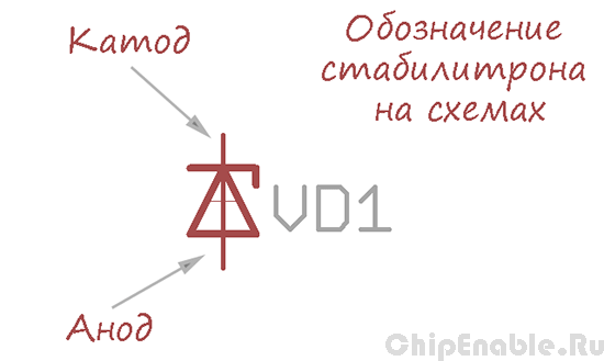
Designation zener
Electrical schematic zener diode is denoted with a little squiggle at the cathode and letter designation VD.
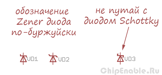
Also there are other embodiments of the zener diode notation used in foreign schemes.
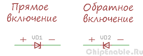
As can be seen from the figure, in two zener output - is the cathode and anode. Consequently, there are only two options for its inclusion:
- inclusion in the forward direction when the anode is connected to the positive supply, and the cathode to the negative,
- inclusion in the opposite direction when the anode is connected to the negative supply and the cathode to the positive.
In the direct inclusion zener behaves like a normal diode, but in the reverse inclusion in Zener breakdown occurs the same. To understand what happens, let's look at the zener voltage characteristic.
How does zener
The right side of the graph - Zener characteristic to which a voltage is applied in the forward direction.The left portion of the graph - Zener characteristic to which a reverse voltage. Similar to the characteristics of the diodes, but the sample (the area where the graph bends) in the zener diode begins much earlier. We are interested in the left side of the graph.
Here we connected to a power source zener diode in the reverse direction and begin to slowly increase the voltage. Until the applied voltage is less than the breakdown voltage, it grows, flows through the zener diode light leakage current Io (microamps, or even less), no breakdown. On this site zener behaves like a resistor with a very high resistance.
At some point, the current starts to increase and the voltage will slow its growth - this means that there is an initial stage of the zener breakdown. Its resistance drops, which can be seen in "necking" the current-voltage characteristics.
Upon further increase the power supply voltage, the current through the zener will increase significantly, and there is no voltage. Zener diode behaves like a resistor with low resistance. This work area characteristics, where the voltage across the zener diode is roughly constant.
again raise the voltage, current continues to grow, the zener starts to warm up. When the current exceeds the maximum allowable value, the zener will overheat and fail.
If you do not bring the case to thermal breakdown and reduce the voltage to zero - voltage characteristic repeated in the opposite direction.
Options zener
What parameters characterize the zener? Basic parameters - the voltage stabilization, stabilization and minimum current dissipation. Zener Ust (foreign literature Uz, Zener Voltage) - is, roughly speaking, the operating voltage of the zener diode. And if you are smart, then the voltage at the zener diode when passing a given current stabilization. Usually one type diodes have a small variation of voltage stabilization, so the documentation specified minimum, nominal and maximum voltage stabilization at a given temperature and current.
Minimum current stabilizatsii Ist min (Iz) - current value at which the zener "out" to your work area current-voltage characteristic. In fact, this is the point at which to start "knee" characteristics.
Power dissipation P Zener - Specifies the maximum zener current. If we assume that the voltage at the zener TT does not change, then the maximum current can be calculated as P / Ust. It is also possible to estimate the maximum current forward P / Uf = P / 0,7. Power dissipation of the zener diode depends on the design of the body (and the area of the pn junction). Typically, this option is listed under "absolute maximum ratings".
Circuit of the zener
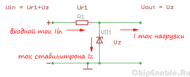
Typical operating circuit Zener - is a simple voltage regulator circuit. It includes a zener diode and a current limiting resistor (power supply and the load on the circuit is not drawn). The input circuit is fed unregulated DC voltage greater than the voltage stabilization at a few volts at the output of a stabilized voltage equal Uz (Zener voltage) used a zener diode.
This voltage regulator can be used to power consumed little schemes , because due to the resistor he can not " give "in the high current load.
As can be seen from the figure, the input current is divided between the zener diode and the load. If the load does not consume current zener "takes" all the current itself, and its value at large may burn. If the load current becomes large, the zener diode "memory" than the current, the voltage across it falls and he can no longer perform their functions.
Resistor R1 is calculated as follows:
R = (Uin - Uz) / (Iz + I)
where Uin - input voltage (V),
Uz - rated voltage of stabilization (B),
Iz - Zener current (A),
I - load current (A).
zener current Iz need to choose between the minimum and maximum values, based on changes in the input voltage and the load current. Minimum current stabilization of a given in the documentation, and the maximum current can be calculated from the maximum power dissipation.


